Your MVHR System – OMNIE Underfloor Heating, Heat Pumps & Ventilation
We - and our partners - use cookies to deliver our services and personalise your experience. By using our website, you agree to the use of cookies as described in our Cookie Policy.
×
Get a Quote
NEW - TorFloor 2
Boiler Upgrade Scheme
Underfloor Heating
Underfloor Heating
Why UFH?
Explore the Range
Floating Floors
Floating Floors
FoilFloat
LowBoard
OMNIE-Tile
Back
Batten Floors
Batten Floors
FoilBatten
TorFloor 2
TorFloor
Back
Suspended Floors
Suspended Floors
FoilBoard
TorFloor 2
TorFloor
Underplate
Back
Screeded Floors
Screeded Floors
ScreedPlate
Staple
Back
Acoustic Floors
Acoustic Floors
New Acoustic Range
TorFloor RdB
LowBoard RdB
FoilFloat RdB
Back
Low Build Up
Low Build Up
LowBoard
Ultimate 2
OMNIE-Tile
Back
Manifolds & Pipe
Manifolds & Pipe
Precision-Flo Manifold
OMNIFLO Pipe
FORMUFLO Pipe
Back
Back
Heat Pumps
Ventilation & Heat Recovery
Smart Controls & Thermostats
Hot & Cold Distribution
System Design
OMNIE for Developers
Technical Library
Technical Library
Datasheets & Guides
Install Videos
FAQs
Back
Case Studies
Get in touch
Book a RIBA CPD Course
About OMNIE
FAQs
Call us today 01392 36 36 05
Home | Resources
Your MVHR System
All

Your MVHR System

UM MVHR 01


Understanding your MVHR system


What is Mechanical Ventilation and Heat Recovery (MVHR)?

  • It is a centralised fan system that extracts moist wet air from bathrooms, kitchens, WC & cloakrooms. The moist air that is extracted passes over a heat exchanger, which then pre-heats the fresh air that comes into the supply valves and rooms such as bedrooms and living areas. This means the energy is recirculated and reduces energy usage, saving on heating bills. The Heat Recovery Unit (HRU) has 2 fans and a single heat exchanger.

Why Use It?

  • This system is used extensively in Germany and properties with low energy design. It means the building can be ‘wrapped up’ and very air tight with minimum energy use. The glazing doesn’t need trickle vents which reduces heat loss and draughts. It increases the amount of air extracted over a longer period to guarantee that the stale air is removed. It provides automatic summer bypass to reduce overheating.

Noise

  • There is some fan noise and this has to be below building regulations level of 30dB in bedrooms. The system is designed to minimise air noise in bedrooms. When the system is in boost (an additional 10% in running capacity) there is a slight increase in fan speed and noise.

How Does it Compare with Normal Extract/Fan Systems?


The heat recovery system runs continuously at a lower rate. Rather than sprinting to extract the stale air as with a conventional extract system the HRU will remove more stale air but over a longer period. This means that to the eye it might appear that there is more steam present but within a short period this will clear, and will be more effective and clearing all the moisture.

Key Points

  1. Reduces energy use in the house by up to 15%;
  2. Reduces stale air and contaminants which can effect health;
  3. Provides fresh air that is filtered through the HRU;
  4. Cutting edge design;
  5. It provides summer bypass which will assist in reducing the air temperature
    and cooling effect.

Maintenance

  •  The machine has an automatic filter warning detector so will come up on the display if there is a problem. We suggest that the filters are checked every 6 months and can be cleaned using a vacuum. If the filters are damaged or worn then replacements are available. Separate filters that can be inserted in the kitchen extract valves are available to remove contaminants in the air.


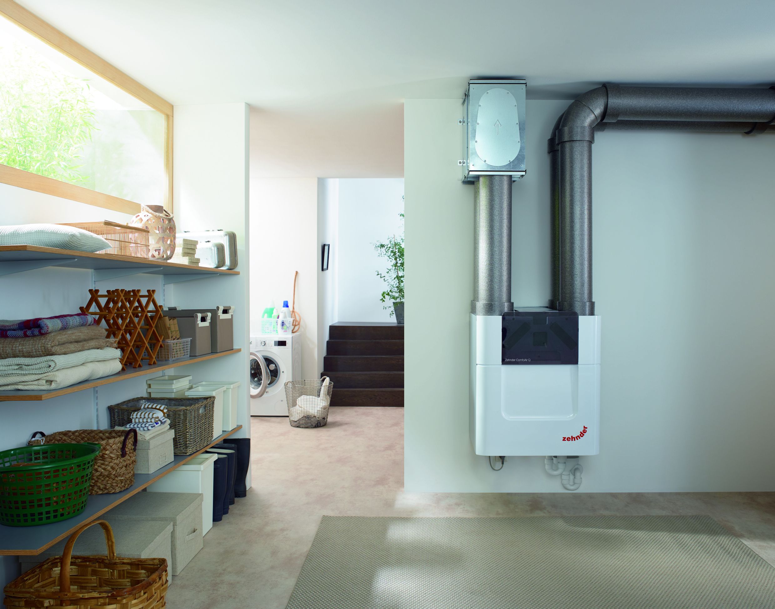
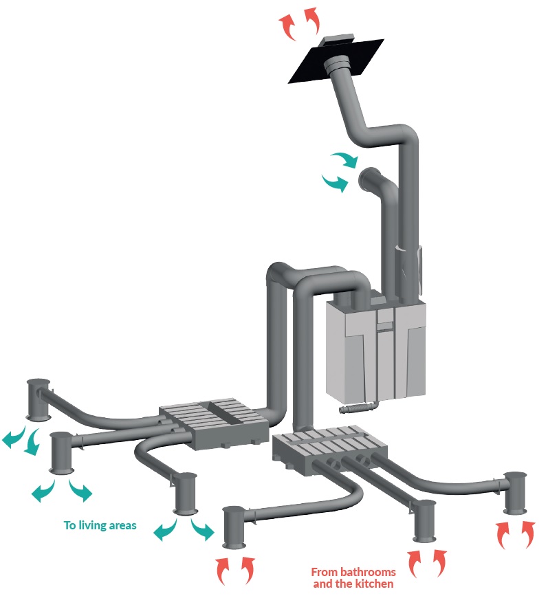
The unit is a balanced ventilation system with heat recovery in order to create energy-efficient ventilation in houses. Balanced ventilation means that pollutants from the kitchen, bathroom, WC(s) and possibly the utility room are extracted, while the same amount of fresh air is supplied into the living room and bedrooms. Gaps under or near doors ensure a good through-flow in the dwelling.


⚠  Ensure that the gaps under or near doors are never obstructed. For example, by furniture, draught excluders or deep-pile carpet.


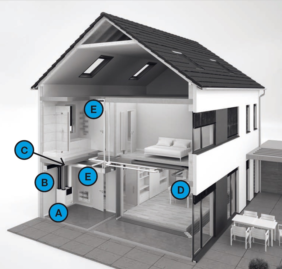
A balanced ventilation system consists of:

  • The unit (A)
  • Duct system for the intake of outdoor air (B)
  • Duct system for the exhaust of indoor air (C)
  • Supply valves and/or grilles in the living room and bedrooms (D)
  • Extract valves and/or grilles in the kitchen, Extract valves and/or grilles in the kitchen,

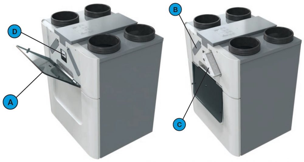
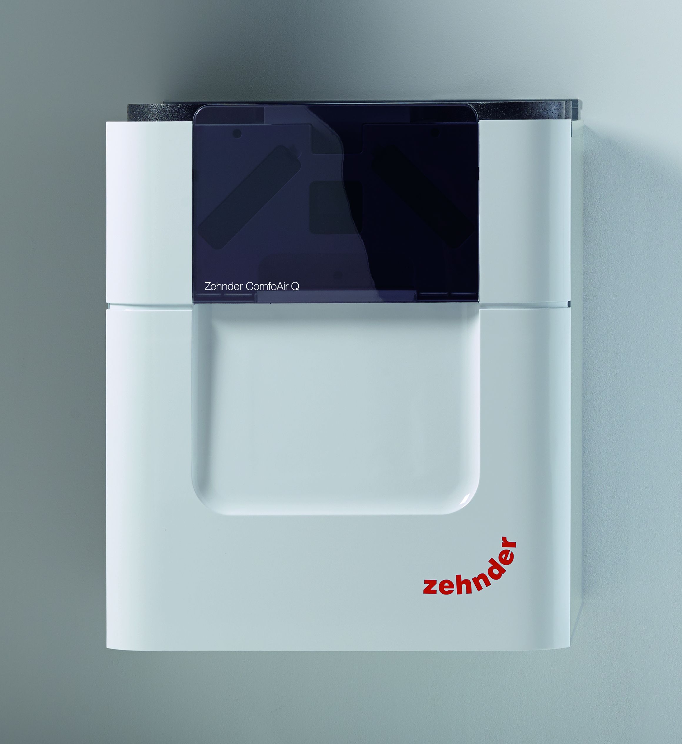
Overview of the unit


PositionPart
ASemi-transparent visor for access to the display and the filter caps.
B2 filter caps for easy access to the filters.
C2 filters for air filtering.
DDisplay to operate the unit.

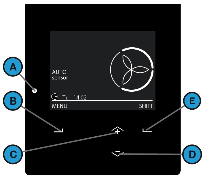
Overview of the display

PositionPart
AStatus indicator LED light.
BUniversal button. The function depends on the current text on the display.
CUp button to: Increase fan speed; Increase value; Select the previous item.
DDown button to: Decrease fan speed; Decrease value; Select the next item.
EUniversal button. The function depends on the current text on the display.

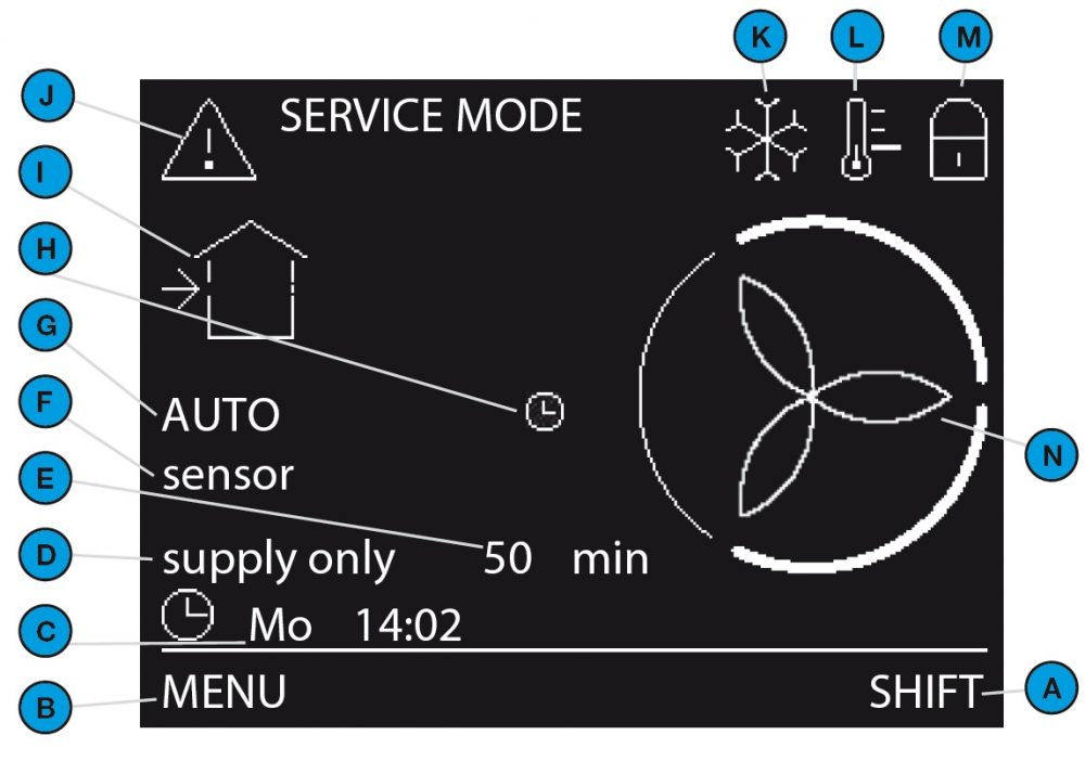
Overview of the basic main screen

The basic mode provides access to general settings and information. The symbol   is displayed in the left top corner of the menus when the basic mode is active.

Position Part
ACurrent function of the universal button below it.
BCurrent function of the universal button below it.
CCurrent day and time.
DCurrent operating function.
ERemaining time of current operating function.
FCurrent sensor mode: SENSOR = sensor is overruling the current set airflow; sensor = sensor can overrule the current set airflow; no text = sensor can not overrule the current set airflow.
GCurrent ventilation mode: AUTO = the airflow is set by the scheduler; MANUAL = the airflow is set by the user.
HTemporary override of the SCHEDULER VENTILATION.
I
J
K
L
M
N

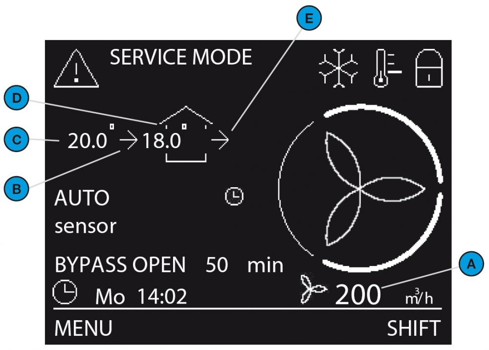
Overview of the advanced main screen

The advanced mode provides access to more detailed information on the settings. All information from the basic mode is also accessible in the advanced mode.
The symbol  is displayed in the left top corner of the menus when the advanced mode is active.


Position Part
ACurrent airflow volume in m3/h or l/s.
BCurrent supply fan mode: no icon = fan is not in operation; -->= fan is in operation.
CCurrent outdoor air temperature in °C or °F. (Only visible when the supply fan is active)
DCurrent supply air temperature °C or °F. (Only visible when the supply fan is active)
ECurrent extract fan mode: no icon = fan is not in operation; --> = fan is in operation.

Overview of the visual signals of the LED
StatusFunction
OnThe unit is operating correctly.
OffThe display is in use or there is no power.
Flashing slowly, every second.Warning: Change filters; SERVICE MODE.
Flashing rapidly, four times a second.Error.

Certification and Warranty


Warranty Conditions

The unit is covered by a manufacturer’s warranty for a period of 24 months from day of delivery. Warranty claims may only be submitted for material faults and/ or construction faults arising during the warranty period. In the case of a warranty claim, the unit must not be dismantled without written permission from the manufacturer. Spare parts are only covered by the warranty if they were supplied by the manufacturer and have been installed by an approved installer.

The warranty becomes invalid if:

  • The guarantee period has elapsed;
  • The unit is used without filters;
  • Parts are used that have not been supplied by the manufacturer;
  • Non-authorised changes or modifications have been made to the unit;
  • Installation has not been carried out according to the applicable regulations;
  • The defects are due to incorrect connection, inexpert use, or contamination of the system.

On-site (dis)assembly costs are not covered by the terms of the warranty. This also applies to normal wear and tear. Zehnder retains the right to change the construction and/or configuration of its products at any time without being obliged to alter previously delivered products.

Liability

The unit has been designed and manufactured for use in balanced ventilation systems incorporating Zehnder heat recovery systems. Any other application is seen as inappropriate use and can result in damage to the unit or personal injury, for which the manufacturer cannot be held liable. The manufacturer is not liable for any damage originating from:
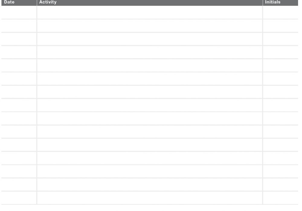
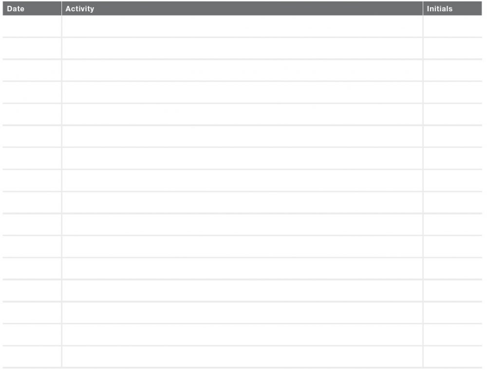
  • Non-compliance with the safety, operating and maintenance instructions in this document;
  • The use of components not supplied or recommended by the manufacturer. Responsibility for the use of such components lies entirely with the installer;
  • Normal wear and tear.


Maintenance


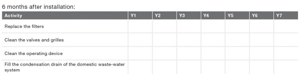
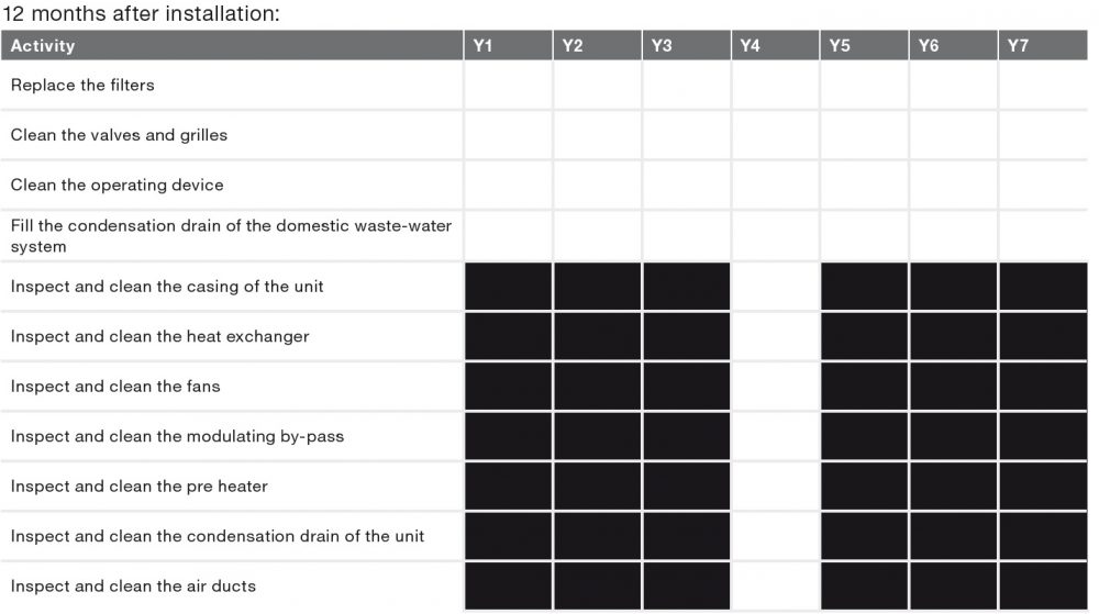
OMNIE recommends you to get a maintenance contract with an expert company. Some installers provide a maintenance contract in which the user maintenance can be integrated.

⚠ Do not disconnect the power of the unit, unless told otherwise in the manual of the unit. This can lead to a build-up of moisture and result in problems with mould.

⚠Do the maintenance tasks within the given periods. If not, the performance of the ventilation system will decrease.

Part of systemLimitResponsibleProcedure
Filters6 monthsUserReplace the filters
Valves6 monthsUserClean the valves
Grilles6 monthsUserClean the grilles
Operating device6 monthsUserClean the operating device
Condensation drain6 monthsUserFill the condensation drain
System inspection and cleaning4 yearsInstaller or service engineer-

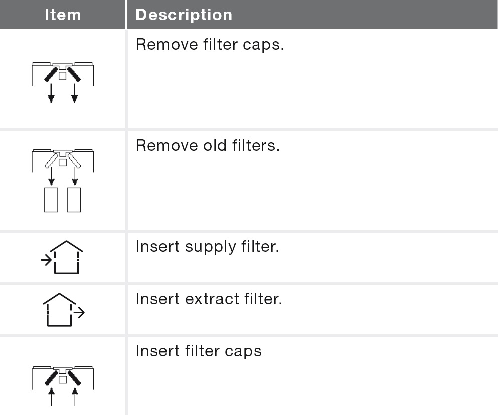
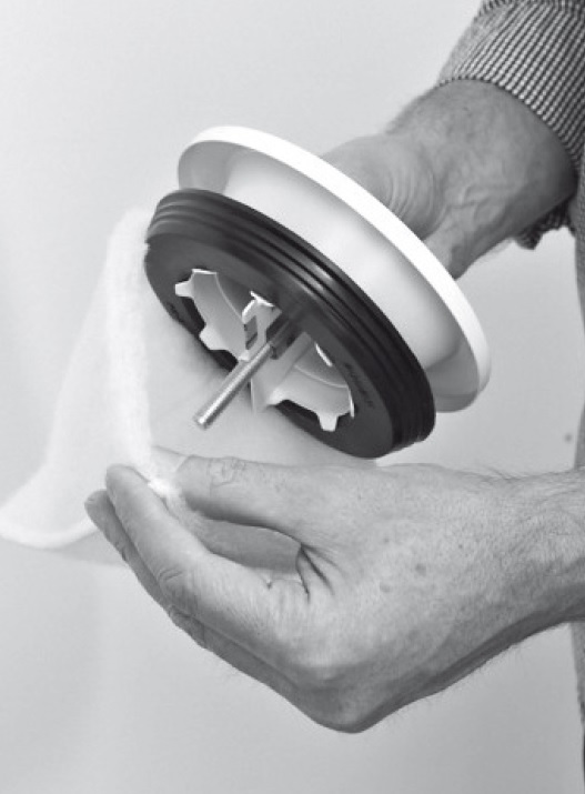
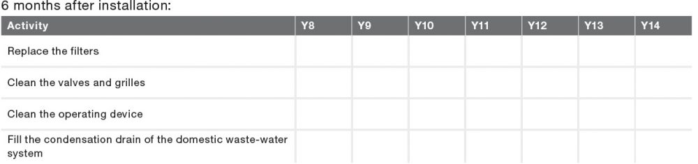
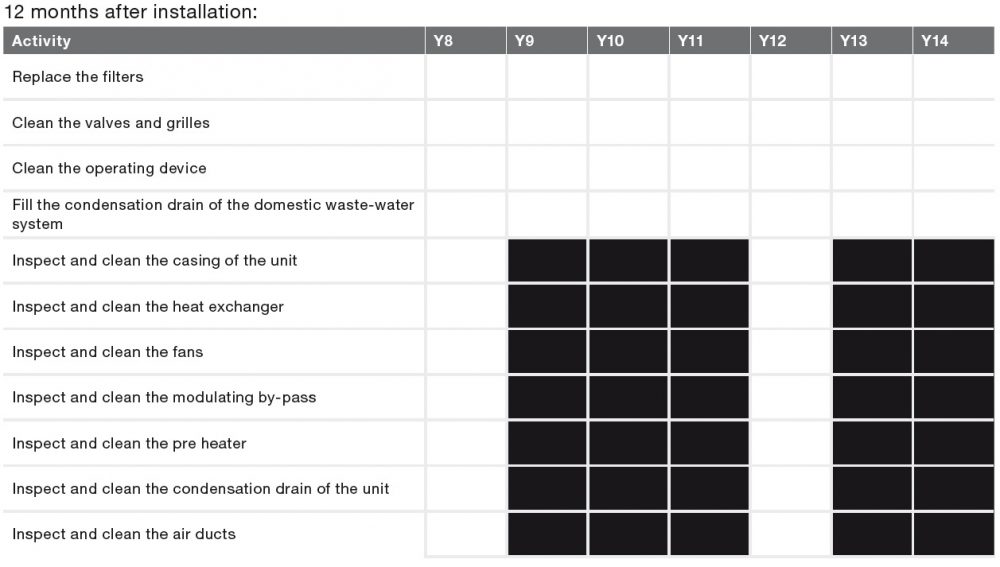
Replace the Filters:


When indicated you must replace the filters. The indication methods that follow are available:

  • The LED light on the unit flashes;
  • The display on the unit shows the warning message: CHANGE FILTERS NOW;
  • The operating device can show a message. The manual of the operating device contains more information about the indication on filter replacement.

⚠Replace the filters at least every six months. This will insure a comfortable and healthy air quality and will protect the unit from pollution.

When you need to replace the filters:

  1. Order new filters. Contact the installer of the unit for providing the correct filters
  2. Filter set                           Order number
    G4/G4 (1x/1x)                 400502012
    F7/G4 (1x/1x)                  400502013
  3. The warranty becomes invalid if:‌  ‌• Parts are used that have not been supplied by the manufacturer ‌• The unit is used without filters.
  4. When the new filters have arrived open the visor.
  5. Select NOW on the warning message. For safety
    reasons the unit will stop the ventilation during the
    filter replacement instructions.
  6. Follow all the instructions on the display.
  7. – Select NEXT to go forward after every completed instruction.
    – Select BACK to go back to the previous instruction.
  8. Select CONFIRM to close the filter replacement instructions and start up the ventilation again.
  9. Close the visor.

To postpone the filter replacement for one day, select IGNORE on the warning message. If you are ready to start filter replacement before the filter warning re-appears, navigate to CHANGE FILTERS in the FILTERS menu.


Clean the valves:

⚠ Clean any valve present in your home at least every six months.

  1. Keep hold of the valve on its outer edge and pull it completely out of the wall or ceiling with a rotating movement.
    If a rubber ring is fitted: Take care when removing
    the valve to leave the rubber ring in place.
  2. Mark the location an setting of the valve. ‌• Do not change the settings of the valve as it would negatively influence the system
    performance;
    ‌• Do not swap the valves with one another as it will negatively influence the system performance;
  3. Remove the filter behind the valve (if present).                                                                                                                                                                                                                                   
  4. Clean the valve with a soft brush, vacuum cleaner or soapy water.
  5. Rinse the valve well and dry.
  6. Replace the filter behind the valve (if present).
  7. Place the valve back in the wall or ceiling.


Clean the grilles:

⚠Clean any grille present in your home at least every six months.

  1. Keep hold of the grille on its outer edge and pull it completely out of the wall or ceiling (if not screwed down).
  2. Clean the grille with a soft brush or vacuum cleaner.
  3. Clean the filter behind the grille (if present) with soft brush or vacuum cleaner. ‌• Do not remove the foam behind the grille (if
    present) as it would negatively influence the system performance.
  4. Place the grille back in the wall or ceiling.


Clean the operating device:

Clean any operating device present in your home at least every six months. Use a dry duster or vacuum cleaner to remove the dust. Do not use water or any other liquid. Start the child lock on the display, to prevent any changes to the settings caused by accidentally pressing the buttons.


Fill the condensation drain:

The condensation drain is connected to the domestic waste-water system. To prevent sewer smells from entering your home, the water seal of the domestic waste-water system must always contain water. You can achieve this by pouring a cup of water into the water seal.


Malfunctions

In the event of a malfunction:

  • the LED light on the unit flashes;
  • the display on the unit shows the corresponding malfunction code(s);
  • the operating device can show a message. The manual of the operating device contains more information about the indication method.

The power to the unit should not be disconnected unless the unit is to be taken out of service due to a serious malfunction or any other compelling reasons.

⚠Do not disconnect the power of the unit, unless told otherwise in the manual of the unit. This can lead to a build-up of moisture and results in problems with mould.

☞ When the unit is installed in an area with a higher average humidity (such as bathroom or wc) the probability of condensation on the outside of the unit is high. This is almost the same as condensation on a window, on which no action is needed.

In the event of a filter malfunction, replace the filter as described in the maintenance chapter.

In the event of all other malfunctions follow these steps:

  1. Navigate to RESET ERROR.
  2. Select CONFIRM.
  3. Wait for 5 minutes.

If the error reoccurs:

  1. Navigate to STATUS.
  2. Navigate to CURRENT ERRORS.
  3. Write down all the malfunction code(s) (Select
    NEXT to view more errors).
  4. Select BACK.
  5. Navigate to UNIT
  6. Navigate to HRU TYPE.
  7. Write down the unit type.
  8. Close the visor.
  9. Contact the installer or service engineer and give
    him the noted information.


Safety

Safety Instructions

  • Always obey the safety regulations, warnings,  comments and instructions given in this  document. When the safety regulations, warnings, comments and instructions in this document are  not obeyed personal injury or damage to the unit
    can occur.
  • After installation all parts that can cause personal  injury are secured behind the casing. You need  tools to open the casing.
  • The installation, commissioning and maintenance  must be carried out by a certified engineer unless  the instructions state otherwise. A non-certified engineer can cause personal injury or damage the performance of the ventilation system.
  • Do not modify the unit or the specifications given in this document. A modification can cause personal injury or damage the performance of the ventilation system.
  • Do not disconnect the power of the unit, unless told otherwise in the manual of the unit. This can lead to a build-up of moisture and result in problems with mould.
  • Replace the filters (at least) every six months. This will ensure a comfortable and healthy air quality and will protect the unit from pollution.
  • Do not open the casing. The installer makes sure that all parts that can cause personal injury are behind the casing.
  • Place the user manual back on the unit after use.
PRODUCTS
  • Underfloor Heating
  • Network Controls
  • Heat Pumps
INFORMATION
  • About Us
  • Resources
  • FAQs & Support
  • Terms & conditions
  • Privacy & Cookie Policy
FOLLOW US
  • Twitter
  • Facebook
NEWS & UPDATES

© OMNIE