Installation of the CQ HRU (CQ 350/450 & 600) – OMNIE Underfloor Heating, Heat Pumps & Ventilation
We - and our partners - use cookies to deliver our services and personalise your experience. By using our website, you agree to the use of cookies as described in our Cookie Policy.
×
Get a Quote
NEW - TorFloor 2
Boiler Upgrade Scheme
Underfloor Heating
Underfloor Heating
Why UFH?
Explore the Range
Floating Floors
Floating Floors
FoilFloat
LowBoard
OMNIE-Tile
Back
Batten Floors
Batten Floors
FoilBatten
TorFloor 2
TorFloor
Back
Suspended Floors
Suspended Floors
FoilBoard
TorFloor 2
TorFloor
Underplate
Back
Screeded Floors
Screeded Floors
ScreedPlate
Staple
Back
Acoustic Floors
Acoustic Floors
New Acoustic Range
TorFloor RdB
LowBoard RdB
FoilFloat RdB
Back
Low Build Up
Low Build Up
LowBoard
Ultimate 2
OMNIE-Tile
Back
Manifolds & Pipe
Manifolds & Pipe
Precision-Flo Manifold
OMNIFLO Pipe
FORMUFLO Pipe
Back
Back
Heat Pumps
Ventilation & Heat Recovery
Smart Controls & Thermostats
Hot & Cold Distribution
System Design
OMNIE for Developers
Technical Library
Technical Library
Datasheets & Guides
Install Videos
FAQs
Back
Case Studies
Get in touch
Book a RIBA CPD Course
About OMNIE
FAQs
Call us today 01392 36 36 05
Home | Resources
Installation of the CQ HRU (CQ 350/450 & 600)
All

Installation of the CQ HRU (CQ 350/450 & 600)

IG MVHR 06

Installation on the wall


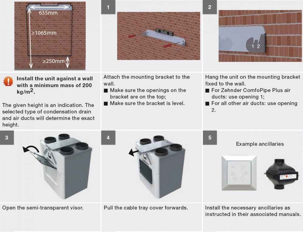
Installation of the condensation drain


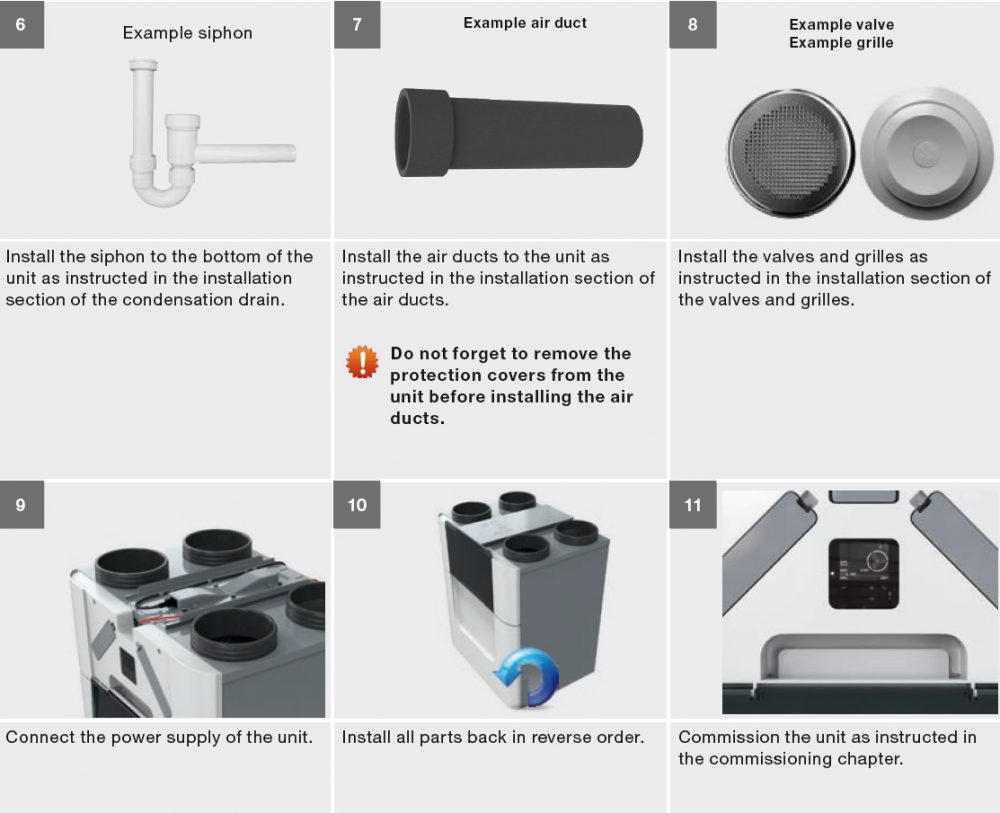
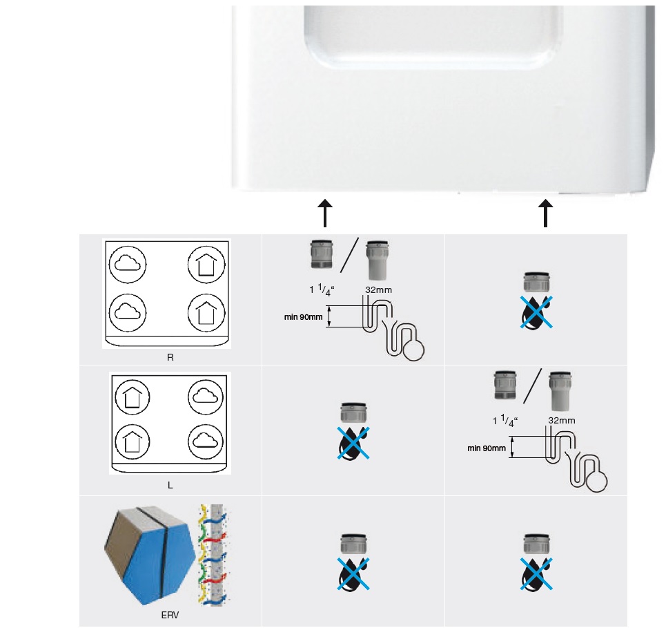
The condensation created by the unit must be drained off frost-free, at a gradient and incorporate an air seal. To drain the condensation from the unit, two bayonet connections are located on the bottom of the unit. These connections are not air tight. Thus it is necessary to close off these connections with the separately delivered sealing cap(s) or with a dry siphon.

⚠ Do not install a water lock (U-bend) on to the unit. On warm days the water will evaporate from the siphon.

Enthalpy exchanger installed:

When the unit is fitted with an enthalpy exchanger the humidity from the extracted air is partly transferred to the fresh supply air. In this case there is no need to condensate to be drained from the unit.

When no dry siphon is installed, seal off both Omnie bayonet connections with the separately delivered condensation drain sealing caps. The unit is not airtight if these connections are left open.

☞ When desired you can always connect a dry siphon to a bayonet connection.


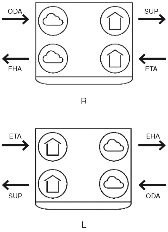
Installation of the air ducts


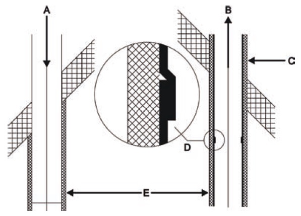
The unit is supplied with a semi rigid system and manifold. When installing an Omnie air duct system read its installation instructions first. The next aspects must always be kept in mind during the installation of the air ducts:

⚠Always connect air ducts of at least 900mm to the unit before you connect the power to the unit. This ensures the motor cannot be touched while the unit is active.

  • The distance (E) between the opening of the outdoor air duct (A) and the opening of the exhaust air duct (B) must be at least 1.5 m;

  • The position of the outdoor air opening (A) relative to other possible sources of stale air is very important (other exhaust-air outlets, street versus garden, etc.);

  • Drain the exhaust duct (D) in the direction of the unit.

  • Insulate the outdoor air duct and the exhaust air duct between the roof/wall passage to render the unit damp proof. This prevents the formation of condensation on the outside of the ducts;

  • Omnie recommends that you fit thermal and damp-proof insulation to the supply duct from the unit up to the supply valves and or grilles. This will prevent unnecessary temperature loss in the summer and winter;

  • Install the air duct with as little air resistance as possible and free from air leakage;

    Size      Minimum air ducts ø

    350       150mm

    450       180mm

    600       180mm

  • Make sure the inside of the air ducts do not have an obstruction of any sort. Air ducts must not have sharp bends, dents or long screws inside. Obstructions will compromise the performance and maintenance of the system;

  • Install a silencer directly onto the supply air and extract air connections and ensure it is straight. For relevant recommendations, please contact Omnie;

CodeMeaning
ODAOutdoor air
SUPSupply air
ETAExtract air
EHAExhaust air
RSupply and extract air to the right side
LSupply and extract air to the left side

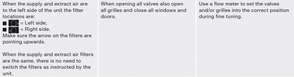
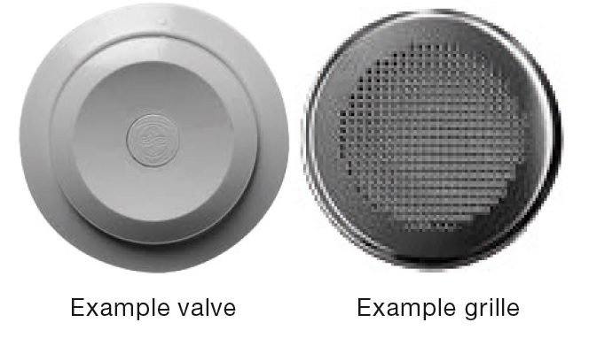
Installation of the valves and/or grilles


  • Install supply and extract valves and/or supply and extract grilles (e.g. in an open living kitchen) at least 1m from each other. This will prevent the supply air short circuiting with the extract air;

  • Use clean sector valves when the valves are installed close to the wall. This will keep the walls clean;

  • To ensure good transfer of air throughout the dwelling, there should be a grille or gap near the inside doors. The grille or gap must provide an overflow of at least 12cm2 per l/s. This is equivalent to: A gap under the inside doors of minimum area 7600mm2 above the floor finish; A gap under the inside doors of at least 10mm for a standard 760mm width door.   


⚠ Do not obstruct these openings. For instance with furniture, draught excluders or deep pile carpet, as the airflow in the house will stagnate.


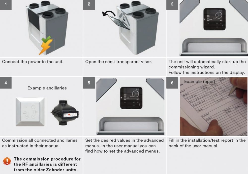
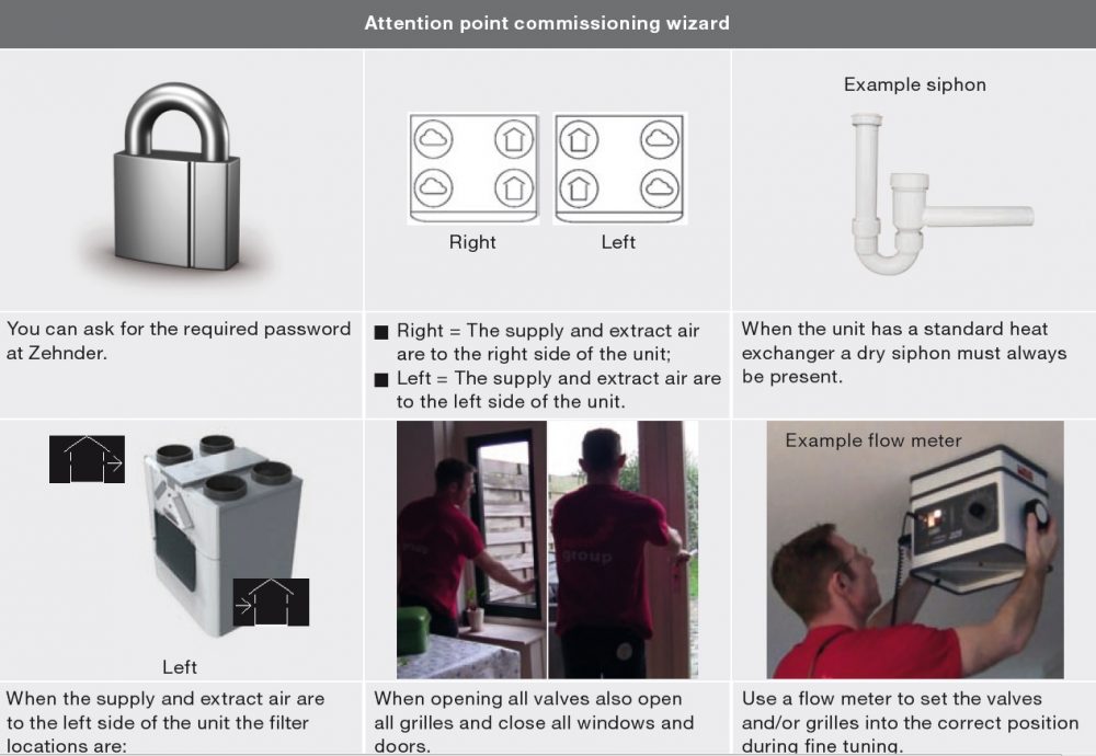
Commissioning procedures


Omnie recommends cleaning the air ducts before commissioning the unit when the dwelling is being occupied. This will prevent damage to the furniture from building dust blown out of the air ducts.


PRODUCTS
  • Underfloor Heating
  • Network Controls
  • Heat Pumps
INFORMATION
  • About Us
  • Resources
  • FAQs & Support
  • Terms & conditions
  • Privacy & Cookie Policy
FOLLOW US
  • Twitter
  • Facebook
NEWS & UPDATES

© OMNIE