ComfoConnect LAN C – OMNIE Underfloor Heating, Heat Pumps & Ventilation
We - and our partners - use cookies to deliver our services and personalise your experience. By using our website, you agree to the use of cookies as described in our Cookie Policy.
×
Get a Quote
NEW - TorFloor 2
Boiler Upgrade Scheme
Underfloor Heating
Underfloor Heating
Why UFH?
Explore the Range
Floating Floors
Floating Floors
FoilFloat
LowBoard
OMNIE-Tile
Back
Batten Floors
Batten Floors
FoilBatten
TorFloor 2
TorFloor
Back
Suspended Floors
Suspended Floors
FoilBoard
TorFloor 2
TorFloor
Underplate
Back
Screeded Floors
Screeded Floors
ScreedPlate
Staple
Back
Acoustic Floors
Acoustic Floors
New Acoustic Range
TorFloor RdB
LowBoard RdB
FoilFloat RdB
Back
Low Build Up
Low Build Up
LowBoard
Ultimate 2
OMNIE-Tile
Back
Manifolds & Pipe
Manifolds & Pipe
Precision-Flo Manifold
OMNIFLO Pipe
FORMUFLO Pipe
Back
Back
Heat Pumps
Ventilation & Heat Recovery
Smart Controls & Thermostats
Hot & Cold Distribution
System Design
OMNIE for Developers
Technical Library
Technical Library
Datasheets & Guides
Install Videos
FAQs
Back
Case Studies
Get in touch
Book a RIBA CPD Course
About OMNIE
FAQs
Call us today 01392 36 36 05
Home | Resources
ComfoConnect LAN C
All

ComfoConnect LAN C

IG MVHR 03

Introduction

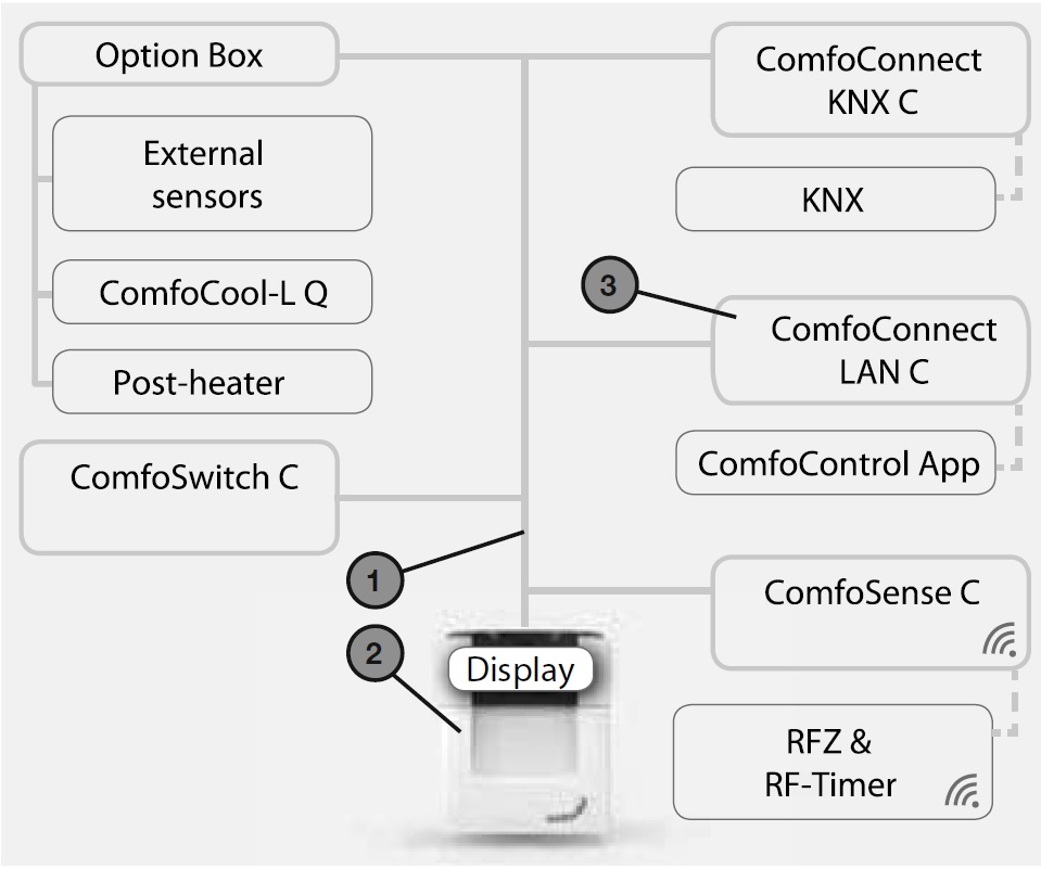
The ComfoConnect LAN C device makes the connection between the home ventilation unit and the ‘Zehnder ComfoControl’ App. The ComfoConnect LAN C can be combined with the ComfoAir Q, Comfort Vent Q or the Aeris NEXT and corresponding App (for the installer and end-user). The ComfoConnect LAN C can control one ventilation unit via the App.

The ComfoConnect LAN C can be wallmounted, with the power supply coming from the ventilation unit via the 4-core ComfoNet cable.


#Description
1ComfoNet interface Protocol over a combined serial bus with a +12V DC power supply.
2Ventilation unit Provides e.g. The + 12V power supply for all the nodes (components) of the ComfoNet.
3ComfoConnect LAN C

Using the ComfoConnect LAN C


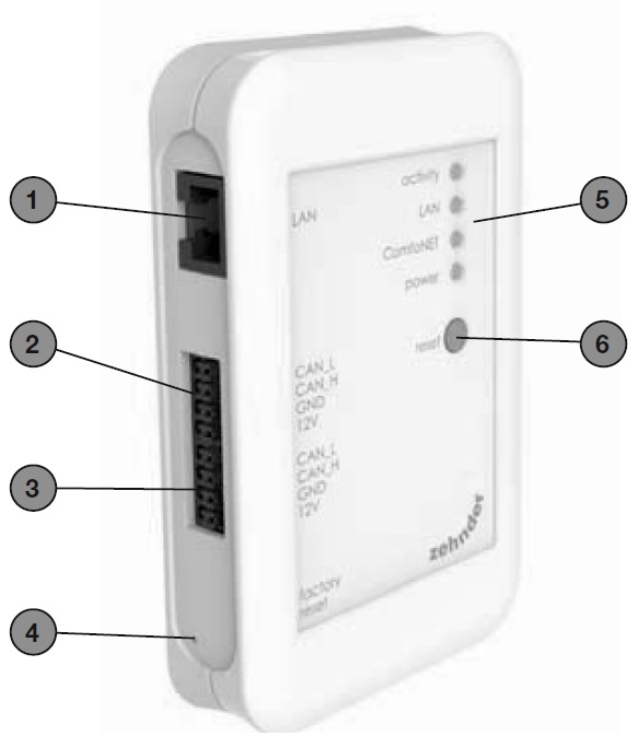
(*1) The 2nd connection can be used as the so-called ‘feed-through/chain’ loop-through connection that includes the +12V DC power supply for the other nodes on the ComfoNet.

(*2)The ‘Factory reset’ button is only accessible by inserting a pin or paper clip into the little hole.


#Description
1LAN connection (RJ45) to network.
21st connection to the ComfoNet network (e.g. ventilation unit, ComfoSense C or ComfoSwitch C), incl. +12V DC power supply of the ventilation unit.
3 (*1)2nd connection to the ComfoNet network (e.g. ventilation unit, ComfoSense C or ComfoSwitch C), incl. +12V DC power supply of the ventilation unit.
4 (*2)Factory reset button for implementing the factory settings.
5Status of indicator LEDs.
6Reset button for restart.

LED Status indicator during normal use
LEDSTATUSDescription
activityOnComfoConnect LAN C is connected to the Internet for remote access via the App.
activityFlashingApp activity.
LANOffLAN cable not connected or DHCP server not found.
LANOnConnected to LAN.
LANFlashingLAN activity.
ComfoNetOnConnected to ComfoNet.
ComfoNetFlashes 1x per secondBusy with connection to ComfoNet.
ComfoNetFlashes 8x per secondThere is a problem with the connection to the ComfoNet and/ or the cabling.
powerOnConnection with the +12V DC power supply.


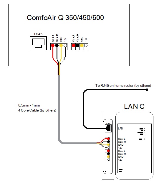
Resetting – The Reset button can be used for a forced restart of the ComfoConnect LAN C in which all the parameter settings in the software remain unchanged.

Factory reset – With the ‘Factory reset’ button all the software parameters of the ComfoConnect LAN C can be put back to the original factory settings. Simply press the Factory reset button for a few seconds until the Power LED starts flashing.

Malfunction checks –

1. Check for a Network and Internet connection.

2. Check the connections to the ventilation unit and the corresponding ComfoNet cables. Ensure the correct colour coding of the connecting cable matches the bus port connection. They must correspond with each other.

As shown in the following images, the colour coding table below is the connection which needs to be made between the Lan C box and the front of the unit.

(Check whether the +12V DC voltage is present)

ComfoNet connectionColour coding (cable & connection)
CAN_LWhite
CAN_HYellow
GNDBlack
12VRed


The additional connections on the Lan C box are to replace the terminals used on the front of the unit, so if you wanted to use an additional controller, you would have to wire this into the connection box.


Technical specifications
Electrical
Nominal input voltage+12V DC
Input voltage range12V DC +/- 20%
Nominal input current0.06 A
Electrical separation1500 V AC (60 sec)
Nominal power consumption0.72 W
Maximum power consumption1.00 W
Maximum ‘loop-through’ current3.20 A

Environmental
Operating temperature-20°C to +60°C
Storage and transportation temperature-40°C to +80°C
Humidity< 95%
Level of protectionIP classification 30 Contamination level PD3 (boiler room)
Combustibility classification of connectorsUL 94 V0
Combustibility classification of housingUL 94 HB (< 20J)
Combustibility classification of PC boardUL 94 V0
Housing materialABS
Weight90 grams

Standard
SafetyEN60950-1
Electromagnetic Compatibility (EMC)CISPR22, EN61000-6-3, EN61000-6-1, EN50491-5-1, EN50491-5-2
Environmental and surroundings requirementsRoHS, REACH. WEEE

Software
LANIPv4 with DHCP or AUTOIP
(Includes a Matrix SSLTM Security software licence from INSIDE Secure)

Installation


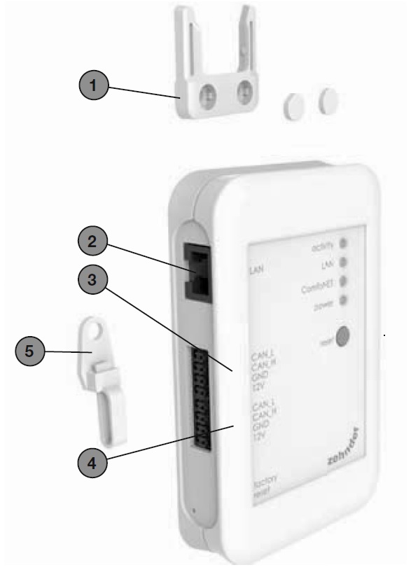
Disconnect the power from the ventilation unit before installing the equipment. Always observe the local safety regulations.

The cable requirements for the ComfoNet interface are as follows:

  • Maximum length: 50m;
  • Number of cores: 2×2 (twisted pair);
  • Screening: not screened;
  • Core: rigid (solid) wires for insertionelements;

  • Colours: compatible with connectors
  • Minimum Ø: 0.2mm2;
  • Optimum: DIN VDE 0281: J-Y(St)Y 2 x 2 x 0.6;

  • Maximum Ø: 1.5mm2.

The network requirements are: DHCP server active and Automatic IP address release active.


Installation:

  1. Mount the ComfoConnect LAN C on the wall. Preferably near the ventilation unit.

  2. Connect the Internet (LAN; RJ45, CAT 5 UTP) communication cable to the ComfoConnect LAN C.

  3. Connect the combined bus Power cable on the ComfoNet interface to one of the two bus ports on the ComfoConnect LAN C.

  4. Connect a second combined bus Power cable on the ComfoNet interface to the other available bus port on the ComfoConnect LAN C, for looping through to any other equipment in the network, such as a ComfoSense C or a ComfoSwitch C.

  5. Mount the pull relief to the wall and use it as a cable opening for all cables from and to the ComfoConnect LAN C. This prevents the cables from the equipment being pulled.

  6. Connect the combined bus Power cable on the ComfoNet interface to one of the two bus ports on the ventilation unit.

  7. Turn on the power.
  8. Download App to control the HRU, visit        http://www.zehnder.co.uk/%3Cfront%3E%3C/front%3E


#Description
1ComfoConnect LAN C wall mounting.
2LAN RJ45 cable connection to network (Router) or wifi router of the ComfoConnect LAN Kit C.
31st connection to the ComfoNet (e.g. ventilation unit), incl. +12V DC power supply of the ventilation unit.
42nd connection/loop-through to the ComfoNet (e.g. ComfoSense C or ComfoSwitch C), incl, +12V DC loop-through power supply of the ventilation unit.
5Cable lead-through and pull relief incl. wall fixture.

Commissioning


Download the ‘Zehnder ComfoControl’ App from the Apple App Store or Google Play Store.

Follow the instructions in the App to establish a connection with the ComfoConnect LAN C. But first the device on which the App is to run must be connected with the same network as the ComfoConnect LAN C.

Further settings for the ComfoConnect LAN C, such as enable/block secure remote access, can be found in the App.

Maintenance: Remove dust regularly from the unit with a dry duster.


Guarantee


The unit is covered by the manufacturer’s warranty for a period of 24 months following installation, and up to a maximum of 30 months following the date of manufacture.

The warranty is rendered invalid if:

  • installation of the unit was not carried out in accordance with the proper instructions;

  • defects have occurred due to incorrect connection, incompetent use or contamination of the system;

  • spare parts used that were not originally supplied by the manufacturer, or repairs done by unauthorised persons.

The costs associated with dismantling and reinstalling at the location are not covered by the warranty. This also applies to normal wear and tear. The manufacturer retains the right to change and/or reconfigure its products at any time without any obligation to alter previously delivered products.


PRODUCTS
  • Underfloor Heating
  • Network Controls
  • Heat Pumps
INFORMATION
  • About Us
  • Resources
  • FAQs & Support
  • Terms & conditions
  • Privacy & Cookie Policy
FOLLOW US
  • Twitter
  • Facebook
NEWS & UPDATES

© OMNIE