Staple System Install Guide
| Stage 1 - Storage and floor preperation |
|---|
NOTE: If it is necessary to store the system once you have taken delivery, ensure it is kept in the following conditions:
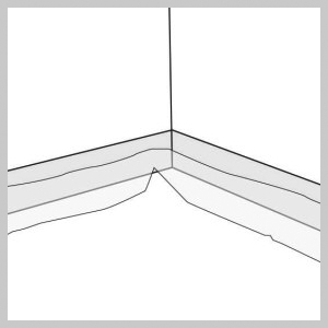
Ensure existing slab meets at least SR2 (5mm deviation in 2m) requirements for floor regularity (BS8204) and preferably SR1 (3mm deviation in 2m). Lay the expansion foam around the perimeter of the room, ensuring the gaiter is facing into the room. The expansion foam should be fitted to the full depth of the floor insulation and screed. NOTE: Where the expansion foam is installed on external walls, additional insulation will be required for compliance with building regulations. |
|
| Stage 2 |
|---|
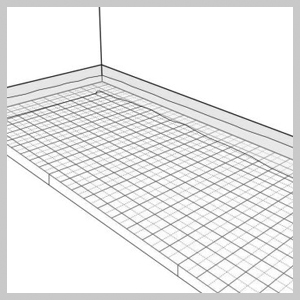
Lay insulation in accordance with building regulation requirements. The insulation should be laid hard up against the expansion foam with no gaps. Ensure that the foams’ gaiter is lying on top of the insulation to prevent the screed from flowing under the insulation. NOTE: When working with any wood or insulation based products, dust and partials can become airborne and pose a hazard to health. This is particularly relevant when machining, cutting or routing. Please follow the relevant guidelines in the product safety datasheets (available on request) on reducing the risk of dust inhalation. |

|
| Stage 3 |
|---|
Prior to laying the underfloor heating pipe, the insulation layer may need to be covered and fully taped with overlapping polyethylene sheets/membrane. NOTE: Preparation and requirements for specialist screeds should be sought from the installation and screed supplier/manufacturer. |
|
| Stage 4 |
|---|
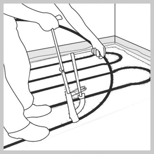
Referring to the OMNIE CAD design, lay the pipe to and from the manifold at the appropriate centres by pre-marking the insulation to provide a guide. The minimum temperature for laying the pipe should be +5°C. Fix the pipe in place with staples by hand or using a pipe stapler (available from OMNIE) with one fixing every metre and with up to 7 around a loop (see below) to a maximum bending radius of 250mm. Depending on the grade of insulation, additional staples may be necessary. Repeat until all circuits are laid. NOTE: If the pipework is kinked during the installation, the coil must be replaced or repaired with an OMNIE connector and then pressure tested. No connections should be made unless fully accessible following completion of the screed and finished floor. |
|
| Stage 4 - Continued |
|---|
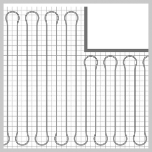
Typically a serpentine pattern is used as shown below. |
|
| Stage 5 |
|---|
Hydraulic pressure test each circuit and keep under pressure whilst screed is being laid. |
|
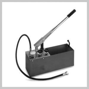
| Quick Guide to Filling the System |
|---|
1. If the manifold is being used to pressure test all circuits at once, close both primary isolation valves. 2. Connect a pressure tester to the drain valve, vent the system of air and increase the pressure to 6 bar. 3. Once at this pressure, leave for 60 minutes. If the pressure has dropped examine the pipework. It may be necessary to pressure test individual circuits to determine if there has been damage to the pipe. 4. If the pressure is maintained and passes the test, record the results on the pressure test certificate. Have the test witnessed and certified by a third party. 5. Maintain this test pressure whilst the screed is being laid. SEE MANIFOLD INSTALLATION GUIDE (DOCUMENT CODE: IG UFH 17) FOR FULL INSTRUCTIONS |

|
| Notes on Expansion Joints |
|---|
For heating screeds intended for the application of stone or ceramic coverings, joint areas shall not exceed 40m2 with a maximum length of 8m. In the case of rectangular rooms, joint areas can exceed these dimensions but maximum to the length relation of 2 to 1. If induced contraction joints are placed in heating screed, these may be cut to a depth of not more than one third of the screed thickness taking into account the location of the pipes and shall be sealed after heating up. Only flow and return pipe should pass through expansion joints. Where this is the case, connecting pipes shall be covered with a flexible insulation tube of some 0.3m in length spanning the expansion joint. |
|
|
| Notes on Screeding |
|---|
It is advisable to keep the system under pressure when laying the screed at a minimum of 6 bar using water. It is essential that the concrete or screed is allowed to fully cure before the underfloor heating system is first put into operation. Any operation of the heating system prior to curing will reduce the moisture content of the screed or concrete and may result in failure of the floor. Initial warm up should take place at least 21 days after the cement screed or in accordance with the manufacturer’s instructions. During the initial heat up, the mixing valve should be set to supply temperature between 20°C and 25°C which needs to be maintained for at least 3 days. After this period, the flow temperature can then be increased to the design maximum and should be held for a further 4 days to complete the process. |
|
|