OMNIE Manifold Install Guide
| Storage |
|---|
NOTE: If it is necessary to store the system once you have taken delivery, ensure it is kept in the following conditions:
|
| 1.0 - Manifold assembly |
|---|
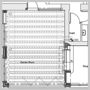
Following the CAD design supplied, locate the manifold(s) in the correct location in the building.
|
|
| 1.1 |
|---|
Securely fix the pre-assembled manifold to the wall, allowing a minimum of 500mm space from the floor to the lowest point of the manifold unit. Allow a minimum 200mm space either side and in front for ease of maintenance. |
| 1.2 |
|---|
Once the brackets are firmly attached to the wall there are two assembly options:
Ensure the valve handles can be easily accessed and turned with no obstructions. Plumb up the primary supply and return pipework to the manifold. The manifold has now been installed and the underfloor heating pipes can now be connected. |
| 2.0 - Connecting the UFH pipework |
|---|
If not already done, install the underfloor heating (UFH) pipes in accordance with the supplied design layout drawings, ensuring sufficient pipe is exposed from the floor to reach the manifold. Curved pipe bends are available to support the pipe as it leaves the floor up to the manifold. Curved pipe bends are available to support the pipe as it leaves the floor up to the manifold. Each pipe must be labelled with the circuit number and the room it serves for identification purposes. Make sure the flow and returns of each pipe run stay together and are labelled ‘flow’ and ‘return’.
|
| 2.1 |
|---|
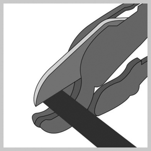
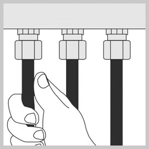
Cut the UFH pipes one pair (flow and return) at a time. Note: cuts should be made with a pipe cutter and should be cut as straight as possible, not an angle.
|
|
| 2.2 |
|---|
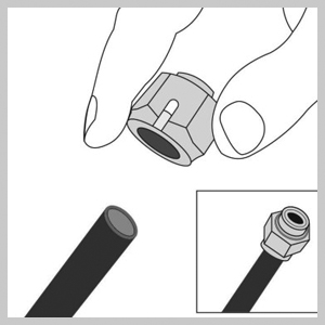
Fit the connectors to the ends on the pipes and connect them to the manifold arms. |
|
| 2.3 |
|---|
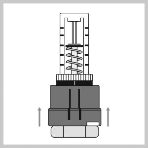
Tip: Cut and fit the pipe connector to one flow pipe and connect this to the top manifold arm first. Then do the return pipe of the same run to the bottom manifold arm. Tighten the connection whilst maintaining upwards pressure on the pipe. These may need to be re-tightened after several heating and expansion cycles. The plumbing of the manifolds should now be complete but remember before continuing to perform a wet pressure test. Ensure all connections are tight, drain-offs closed and all connections have been checked. The UFH system can now be flushed and filled followed by a pressure test. Please ensure you complete and return the pressure testing form (page 6) to validate your warranty. |
|
| 3.0 - Flushing the system |
|---|
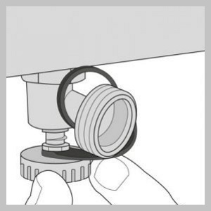
Fill the UFH at the manifold for the first time. Using the heating system filling loop will cause air to get trapped in the UFH pipe runs. Turn off the main manifold isolation valves. Tip: Flush and fill one UFH pipe run at a time. Connect a filling house to the top manifold arm. Connect a drain hose to the bottom manifold arm and open this drain valve. |
|
| 3.1 |
|---|
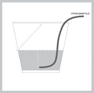
Put the end of the drain hose in a bucket of water. This will show the air being removed from the pipe when filling the system with water. |
|
| 3.2 |
|---|
Turn the water supply on of the supply pipe. Open the drain valve on the top manifold arm connected to the supply pipe.
|
|
| 3.3 |
|---|
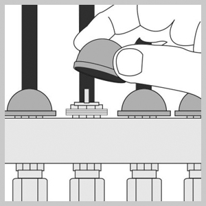
b) Open the corresponding flow meter by lifting the red locking cap and twisting the flow meter on the top manifold arm. c) At this point water should now be flowing into the top manifold, through the open flow meter, around that pipe run and returning through the bottom manifold and out via the drain hose. d) Once all air has been flushed from the pipe run, close the open flow meter and refit the blue cap on the bottom manifold arm. Repeat parts a – d for each of the pipe runs connected to this manifold. Once all pipe runs have been flushed, open all the pipe runs together for one final flushing of the system. |
|
| 3.4 |
|---|
Once all pipe runs have been flushed, open all the pipe runs together for one final flushing of the system. Once completed, close both drain valves and turn off the water supply. |
| 4.0 - Pressure testing the system |
|---|
Connect a pressure test pump to the drain valve on the top arm manifold. Once connected, open the drain valve and start to pressurise the system. Keep checking the pipe connections on the manifold and tighten our reseal if any leaks are found. Vent the system of any residual air then increase the pressure to 6 bar. Initially allow for a 15 minute stabilisation period at 6 bar. If pressure drops, increase back to 6 bar and maintain for a further 45 mins. If pressure remains under, inspect the pipework and manifold for possible leaks. It may be necessary to pressure test individual circuits to determine if there has been damage to a UFH pipe run. Resolve where necessary and repeat the pressure test. Once pressure is maintained consistently, record the results on the pressure test certificate. The installation of the manifold is now complete and the commissioning of the UFH system can now be completed. |
| 5.0. End Notes |
|---|
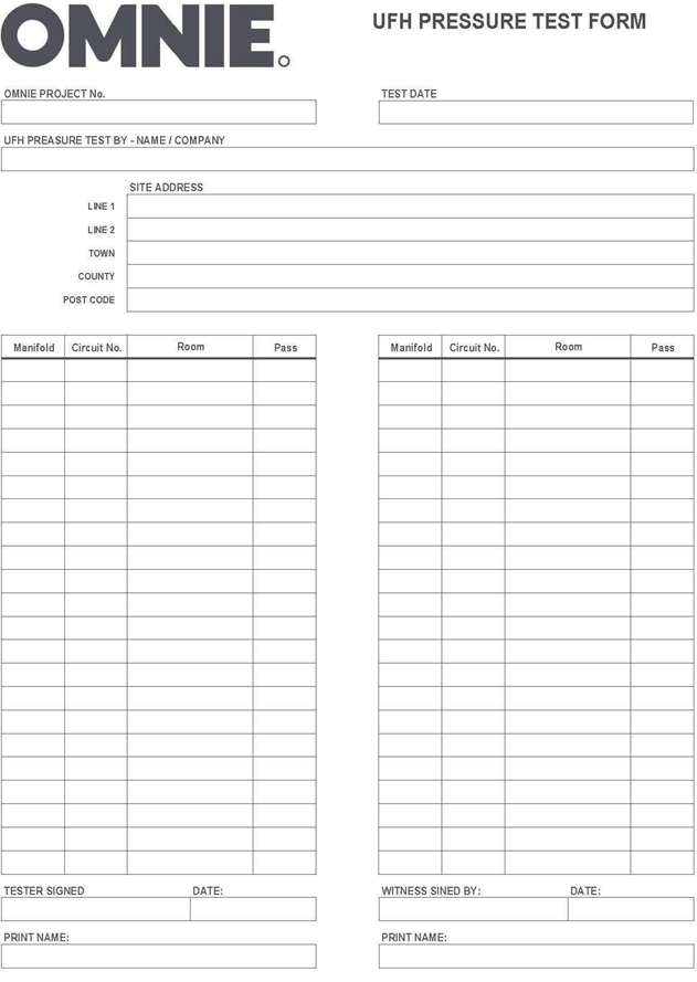
Ensure you complete and return the pressure testing form (see page 6) to validate your warranty. |
| 6.0 UFH PRESSURE TEST FORM (PT UFH 01.1) |
|---|
|