OMNIE HOME Wiring Centre (Wireless) – 230V – Install Guide
| Install Guide |
|---|
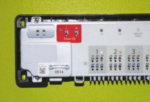
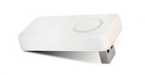
Use the OMNIE Home wireless wiring centre(s) to simply and safely connect thermostats and corresponding actuators. The wiring centre(s) connects wirelessly to the network via the OMNIE Home Gateway which is connects to any WiFi router allowing control of the system via the OMNIE smartphone App, only a single OMNIE Home Gateway is required and can support up to 232 devices. Install the wiring centre next to the UFH manifold, relative air humidity in the room may not exceed 95%. Clean the wiring centre only with a dry and soft cloth. Do not use solvents or aggressive cleaning agents. IMPORTANT: This product must only be installed by a qualified electrician and comply with all installation regulations. NOTE: Each OMNIE Home wireless wiring centre comes with a USB co-ordinator, this allows independent setup if no WiFi network is available, one coordinator can support up to 9 wiring centres, please note this setup does not support app control, for app control you must have the Gateway installed.
Wiring Centre (wireless control)
|
| Stage 1 |
|---|
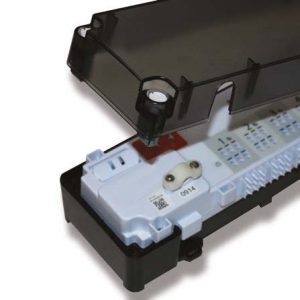
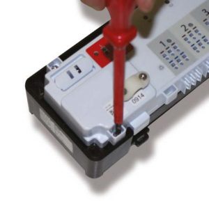
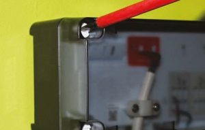
Remove the plastic cover. Open (and close) the four white screws with a quarter turn only. Note that screws on opposite sides turn in the opposite direction.
Unscrew and remove the white terminal connection board. |
| Stage 2 |
|---|
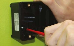
Attach the back of the wiring centre securely to the wall via the 2 screw holes.
|
| Stage 3 |
|---|
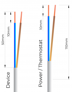
Cut the power and device cable to length.
|
| Stage 4 |
|---|
Reattach the white terminal connection board.
|
| Stage 5 |
|---|
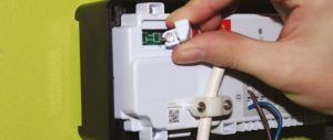
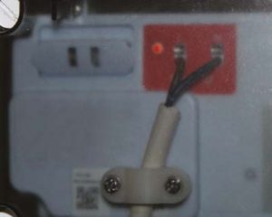
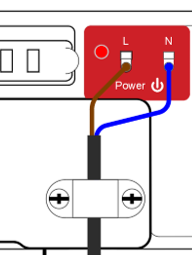
Connecting the Power supply The power supply panel colored red has a Live and Neutral push in style round connectors. With the the power wires prepared (see diagram) push into the respective Live and Neutral round holes, the internal push connector should grip the wire firmly, then attach the white strain-relief using the two screws to secure the mains power wire. Note the rectangle slot above each connection is for releasing the wire if required, this is done by gently inserting the tapered plastic tool provided, this opens the internal grip so the wire can be removed. |
|
| Stage 6 |
|---|
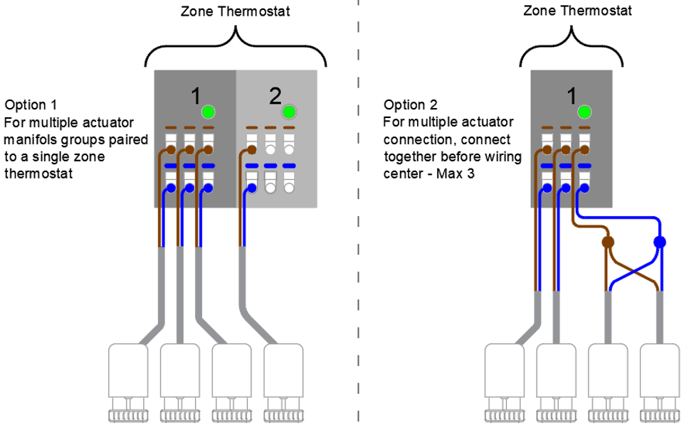
Connecting the circuit actuators With the manifold in place, each circuit/pipe is controlled by its own actuator, in turn circuits are allocated to their specific rooms/areas, so a room/area may have multiple circuits which is to be controlled by a single thermostat, this is called a “Zone”. The circuits should have been labelled as to which room/area they serve, this can also be determined from the CAD design. (circuit numbers always run left to right looking at the manifold) With this information you need to first group the circuits/actuators into their specific zones. Example – 10 circuit manifold with 4 zones/thermostat Circuits – 1,2,3 = Zone 1 (Kitchen) The wiring centre has alternate dark/light grey shaded panels each of these have three actuator connection points available and are numbered 1 to 8, each section is a “Relay” effectively a switch to control the actuators, this allows this wiring centre to manage up to maximum of 8 zones. A thermostat can be configured via the OMNIE app to wirelessly control a single, multiple or all relays on the wiring centre, relays on the wiring centre can be paired in any number/configuration to work from one thermostat. Using the example above the wires from each actuator can now be connected to the wiring centre as follows, Note the internal push connector should grip the wire firmly. Thermostat Zone 1 circuits 1,2,3 – with the actuator’s wires prepared (see diagram) they can now be each pushed into the round connection points in relay number 1, this uses all 3 points in that panel. Thermostat Zone 2 circuits 2,3 – will use only 2 of the 3 points available in relay number 2. Thermostat Zone 3 circuits 4,5,67 – as there are 4 actuators, to connect this it can be done two ways either using 2 relays on the wiring centre i.e. relays 3 and 4 then these are then paired to work together via the thermostat/app. (see note below for the alternative) Thermostat Zone 4 circuit 10 – will use only 1 of the 3 points available in relay number 5. Note Zone 3 – this example does reduce the maximum number of zones that can be controlled from this wiring centre from 8 down to 7 although this is not a problem in this example. If all 8 relays were required to create 8 Zones and a zone/area has more than 3 actuators/circuits some of the actuators from this zone/area will need to be connected together before going to the wiring centre, using a suitable sealed connector, you will need to group the required actuators neutrals and the lives together then from this run a single live and neutral wire to its designated relay on the wiring centre (a maximum 3 actuators per single relay connection on the wiring centre allowing each relay panel on the wiring centre ability to support up to 9 actuators). Note the rectangle slot above each connection is for releasing the wire if required, this is done by gently inserting the tapered plastic tool provided, this opens the internal grip so the wire can be removed.
|
|
| Stage 7 |
|---|
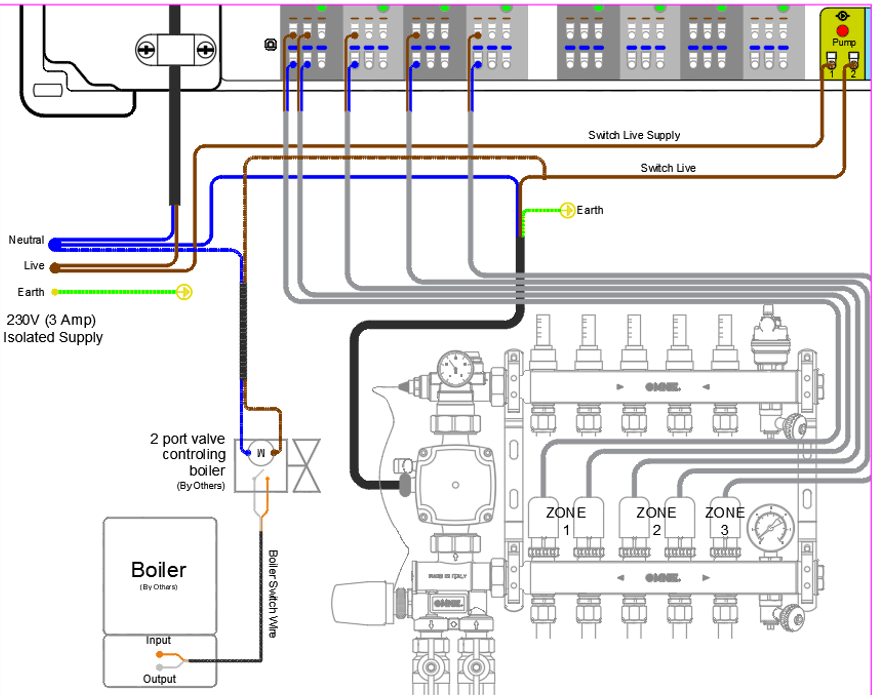
The pump connection on the bottom right of the wiring centre is VOLT FREE so it requires a 230V live supply taken from the same isolated live supplying the wiring centre, then the switched live going to the pump live with neutral and earth coming from isolation direct to the pump.
|
| Stage 8 |
|---|
Boiler connection (always check your boiler instructions/manufacturer with regards to demand switching) It is recommended that each manifold has a 2 port zone valve (not supplied), this is connected into the pump circuit, once energized it will switch a VOLT FREE contact wired to and from the boiler. |
|
| Stage 8a |
|---|
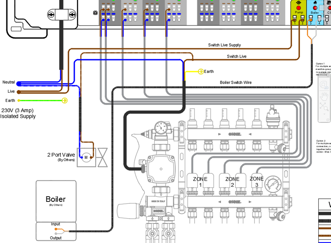
Alternatively you can use the boiler VOLT FREE connection at the bottom right of the wiring centre, connecting switch wires to and from the boiler. |
|
| Stage 9 |
|---|
Attach the red strain-relieving strip using the three screws to secure the wires to the bottom side of the wiring centre.
|
| Stage 10 |
|---|
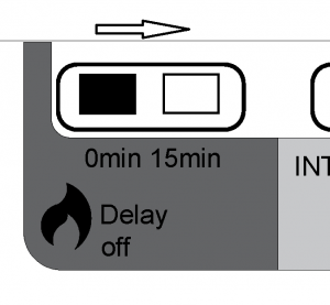
Set the boiler delay, wireless, and thermal actuator jumpers switches at the top right of the wiring centre. Jumper switch settings/positions for pump/boiler on/off delay. The pump/boiler on delay and the pump off delay are fixed at 3 minutes in the software and at 0 in the terminal. The default setting for the boiler off delay is also 0 minutes, but can be changed to 15 minutes. To do this, carefully remove the jumper and re-insert it in the other position as shown below:
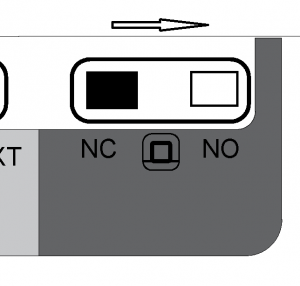
The default setting for the type of actuator is normally closed (NC). To change this setting to normally open (NO), carefully remove the jumper and re-insert it in the other position as shown below (OMNIE use NC actuators). Press the reset button to complete this action. |
| Stage 11 |
|---|
Make sure there is a fuse in the fuse holder.
|
| Stage 12 |
|---|
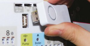
If you have no internet you can manually set up the system, this is done without the app function, plug in the USB co-ordinator (please refer to the co-ordinato set up guide).
|
| stage 13 |
|---|
Reattach the plastic cover.
|
| Stage14 |
|---|
Switch on mains power supply to the unit. The red LED comes on.
|
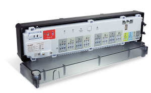
 OMNIE Home Gateway
 Co-ordinator