Filling the Underfloor Heating System
| Stage 1 |
|---|
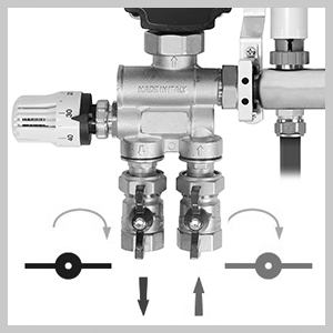
With all pipe circuits connected, the system is ready to be hydraulically filled. Ensure both flow and return primary manifold isolating valves are fully closed.
NOTE |
|
| Stage 2 |
|---|
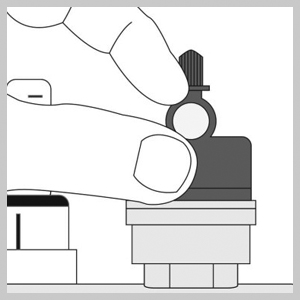
Unscrew the grey nipple on the auto-air vent a 1/4 turn from closed. The black cap is a manual air vent and needs to be on and finger tight.
|
|
| Stage 3 |
|---|
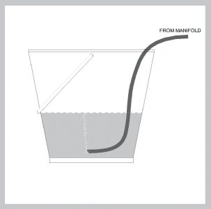
Remove the metal caps on the filling/drain valves on the top and bottom arms of the manifold. Connect a supply hose to the top valve and a drain hose to the bottom valve using suitable fittings. Direct the drain hose into a suitable bucket, keeping the pipe end below the waterline to see all air is expelled. Open both valves fully anticlockwise with the square key located on the caps. |
|
| Stage 4 |
|---|
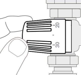
When filling the UFH system at the manifold, first fully open or remove the water mixing valve head.
|
|
| Stage 5 |
|---|
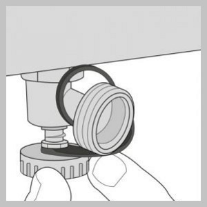
Fill one circuit at a time, unscrew and remove the cap on the return manifold arm of the circuit you wish to fill. Keep all the remaining caps firmly in place.
|
|
| Stage 6 |
|---|
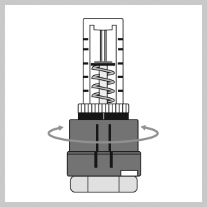
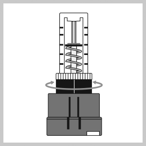
To open the corresponding flow meter of the circuit you wish to fill. This is done by turning the red collar anti clockwise by hand until fully open. Keep the remaining flow meters closed by turning the red collar clockwise until fully closed. For more details, refer to the balancing guide (IG UFH 26.1)
|
| Stage 7 |
|---|
Fill the manifold and the open circuit, letting the water run for minimum of 5 min per circuit until no air bubbles are exiting from drain pipe in the bucket. If the filling and drain hoses are the wrong way round the water will bypass the circuit and air will be trapped in the UFH system. Continue until all circuits are filled at which time all the circuits can be opened together. |
|
| Stage 8 |
|---|
Close the filling/drain valves and disconnect the hoses. |
| Stage 9 |
|---|
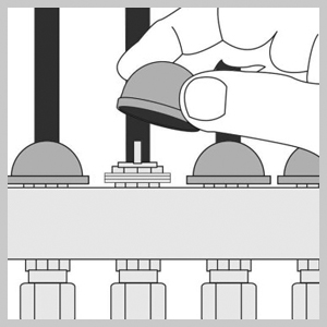
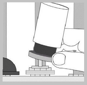
With all caps removed the actuators can now be fitted, install securely by applying a downwards pressure to compress circuit valve spring aligning the threaded collar on the actuator with the valve on the manifold, take care not to cross thread, finger tight is sufficient. |
|
| CONNECTION CHECKLIST |
|---|
|